For the Ford F150 2009, 2010, 2011, 2012, 2013 model year.

Passenger compartment fuse panel Ford F-150.
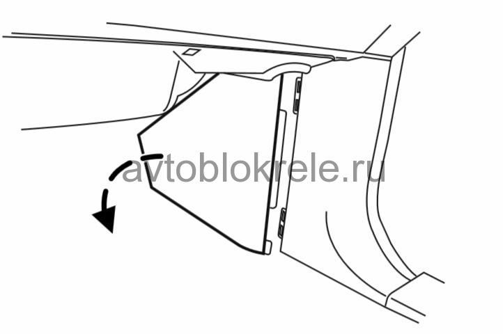
The fuse panel is located under the right-hand side of the instrument panel. To remove the trim panel for access to the fuse box, pull the panel toward you and swing it out away from the side and remove it. To reinstall it, line up the tabs with the grooves on the panel, then push it shut.
How to find fuse box on a Ford F150.
To remove the fuse box cover, press in the tabs on both sides of the cover, then pull the cover off. To reinstall the fuse box cover, place the top part of the cover on the fuse panel, then push the bottom part of the cover until you hear it click shut. Gently pull on the cover to make sure it is seated properly.
Fuses box diagram Ford F-150.
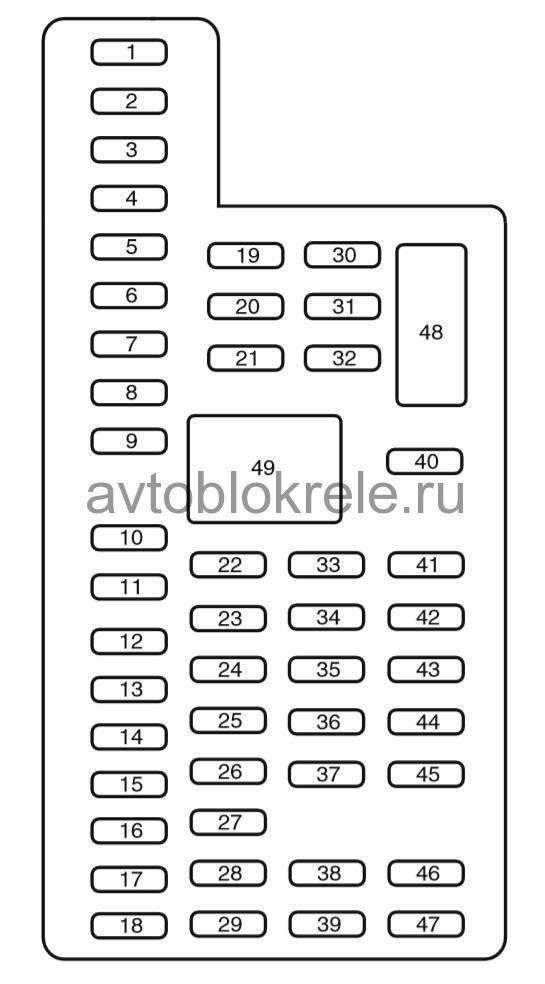
The fuses are coded as follows.
Fuse/Relay Location | Fuse Amp Rating | Protected Circuits |
1 | 30A | Driver side front window |
2 | 15A | SYNC® |
3 | 30A | Passenger side front window |
4 | 10A | Interior lamps |
5 | 20A | Memory module |
6 | 5A | Not used (spare) |
7 | 7.5A | Power mirror switch, Memory seat module |
8 | 10A | Not used (spare) |
9 | 10A | Radio display, GPS module, Navigation display |
10 | 10A | Run/accessory relay |
11 | 10A | Instrument cluster |
12 | 15A | Interior lighting, Puddle lamps, Backlighting, Cargo lamp |
13 | 15A | Right turn signals/stop lamps |
14 | 15A | Left turn signals/stop lamps |
15 | 15A | Reverse lights, High-mounted stop lamp |
16 | 10A | Right low-beam headlamp |
17 | 10A | Left low-beam headlamp |
18 | 10A | Brake-shift interlock, Keypad illumination, PCM wakeup, PATS |
19 | 20A | Audio amplifier |
20 | 20A | Power door locks |
21 | 10A | Ambient lighting |
22 | 20A | Horn |
23 | 15A | Steering wheel control module |
24 | 15A | Datalink connector, Steering wheel control module |
25 | 15A | Not used (spare) |
26 | 5A | Radio frequency module |
27 | 20A | Not used (spare) |
28 | 15A | Ignition switch |
29 | 20A | Radio/Navigation |
30 | 15A | Front parking lamps |
31 | 5A | BOO – IP, BOO – Engine |
32 | 15A | Delay/accessory – moon roof, power windows, locks, Automatic dimming mirror/Compass |
33 | 10A | Heated seats |
34 | 10A | Reverse sensing system, 4×4 switch, Rear video, Off road indicator (SVT Raptor) |
35 | 5A | Hill descent switch (SVT Raptor) |
36 | 10A | Restraint control module, Occupant classification system module |
37 | 10A | Trailer brake control |
38 | 10A | Delayed accessory – 110V power point, Radio (AM/FM) |
39 | 15A | High beam headlamps |
40 | 10A | Rear park lamps |
41 | 7.5A | Passenger airbag deactivation indicator, Upfitter switch (SVT Raptor) |
42 | 5A | Overdrive cancel switch |
43 | 10A | Not used (spare) |
44 | 10A | Not used (spare) |
45 | 5A | Not used (spare) |
46 | 10A | Climate controls module |
47 | 15A | Fog lamps, Exterior mirror turn signals |
48 | 30A Circuit Breaker | Power rear windows, Power sliding back window |
49 | Relay | Delayed accessory |
Power distribution box Ford F-150.
The power distribution box is located in the engine compartment.

The power distribution box contains high-current fuses that protect your vehicle’s main electrical systems from overloads.
ford f150 fuse box location
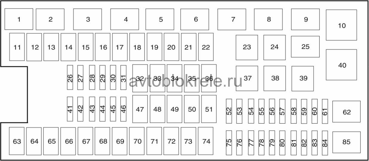
The high-current fuses are coded as follows
Fuse/Relay Location | Fuse Amp Rating | Protected Circuits |
1 |
| Powertrain control module (PCM) relay (3.7L, 5.0L and 6.2L engines) |
2 | — | Starter relay |
3 | — | Blower motor relay |
4 | — | Rear window defroster relay |
5 | — | Electric fan relay (high speed) |
6 | — | Trailer tow (TT) park lamp relay |
7 | — | Run/start relay |
8 | — | Fuel pump relay |
9 | — | TT Battery charger relay |
10 | — | PCM relay (3.5L engine) |
11 | 30A** | Power running board motors |
12 | 40A** | Electric fan |
50A** | Electric fan (6.2L with max trailer tow, SVT Raptor) | |
13 | 30A** | Starter relay power |
14 | 30A** | Passenger power seat |
15 | 40A** | Electric fan |
50A** | Electric fan (6.2L with max trailer tow, SVT Raptor) | |
16 | — | Not used |
17 | 30A** | Trailer brake control |
18 | 30A** | Upfitter 1 (SVT Raptor) |
19 | 30A** | Upfitter 2 (SVT Raptor) |
20 | 20A** | 4×4 module (electronic shift) |
21 | 30A** | TT battery charge relay power |
22 | 20A** | Cigar lighter (cigarette lighter fuse) |
23 | — | A/C clutch relay |
24 | — | Not used |
25 | — | Vacuum pump relay (3.5L engine) |
26 | 10A* | PCM – keep alive power, PCM relay coil, canister vent solenoid (3.7L, 5.0L and 6.2L engines) |
27 | 20A* | Fuel pump relay power |
28 | 10A* | Upfitter 4 (SVT Raptor) |
29 | 10A* | 4×4 IWE solenoid |
30 | 10A* | A/C clutch |
31 | 15A* | Run/start relay power |
32 | 40A** | Rear window defroster relay power, Heated mirror relay power |
33 | 40A** | 110V AC power point |
34 | 40A** | PCM relay power (3.7L, 5.0L and 6.2L engines) |
50A** | PCM relay power (3.5L engine) | |
35 | — | Not used |
36 | 30A** | Roll stability control (RSC)/Anti-lock brake system (ABS) |
37 | — | TT left stop/turn relay |
38 | — | TT right stop/turn relay |
39 | — | TT back-up lamps relay |
40 | — | Electric fan relay |
41 | 15A* | Front camera washer (SVT Raptor) |
42 | 5A* | Run/start coil |
43 | 15A* | TT back-up lamp relay power |
44 | 15A* | Upfitter 3 (SVT Raptor) |
45 | 10A* | Alternator sensor (non-6.2L engines) |
46 | 10A* | Brake on/off (BOO) switch |
47 | 60A** | RSC/ABS module |
48 | 20A** | Moon roof |
49 | 30A** | Wipers |
50 | — | Not used |
51 | 40A** | Blower motor relay power |
52 | 5A* | Run/start – Electronic power assist steering, Blower relay coil |
53 | 5A* | Run/start – PCM |
54 | 5A* | Run/start – 4×4 module, Back-up lamps, RSC/ABS, TT battery charge relay coil, Rear window defroster relay coil, Front camera washer relay coil (SVT Raptor) |
55 | — | Not used |
56 | 15A* | Heated mirrors |
57 | — | Not used |
58 | — | Not used |
59 | — | Not used |
60 | — | Not used |
61 | — | Not used |
62 | — | Wiper motor relay |
63 | 25A** | Electric fan |
64 | 40A** | Vacuum pump relay power (3.5L engine) |
65 | 20A** | Auxiliary power point (instrument panel) |
66 | 20A** | Auxiliary power point (inside center console) |
67 | 20A** | TT park lamps relay power |
68 | 25A** | 4×4 module |
69 | 30A** | Passenger heated/cooled seats |
70 | — | Not used |
71 | 20A** | Heated rear seats |
72 | 20A** | Auxiliary power point (Rear) |
73 | 20A** | TT stop/turn lamps relay power |
74 | 30A** | Driver power seat/memory module |
75 | 15A* | PCM – voltage power 1 (3.7L, 5.0L, 6.2L engines PCM module) |
| 25A* | PCM – voltage power 1 (3.5L engine PCM module) |
76 | 20A* | PCM – Voltage power 2 (General powertrain components, Mass air flow/Intake air temp sensor) (3.7L, 5.0L, 6.2L engines) |
| 20A* | PCM – Voltage power 2 (General powertrain components, Canister vent solenoid) (3.5L engine) |
77 | 10A* | PCM – Voltage power 3 (Emission related powertrain components, Electric fan relays coil) |
78 | 15A* | PCM – Voltage power 4 – Ignition coils (3.5L, 3.7L, 5.0L engines) |
| 20A* | PCM – Voltage power 4 – Ignition coils (6.2L engine) |
79 | 5A* | Rain sensor |
80 | — | Not used |
81 | — | Not used |
82 | — | Not used |
83 | — | Not used |
84 | — | Not used |
85 | — | Electric fan relay (low speed) |
*Mini fuse
**Cartridge fuse
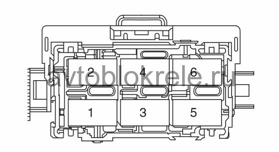
Auxiliary relay box Ford F-150 (SVT Raptor only).
The relay box is located in the left rear corner of the engine compartment.
Fuse/Relay location | Fuse amp rating | Description |
1 | — | Up fitter 1 relay |
2 | — | Up fitter 2 relay |
3 | — | Up fitter 3 relay |
4 | — | Up fitter 4 relay |
5 | — | Front camera washer relay |
6 | — | Not used |
Color of fuses.
Standard fuse amperage rating and color
Fuse ating | Mini fuses | Standard fuses | Maxi fuses | Cartridge maxi fuses | Fuse link cartridge |
2A | Grey | Grey | — | — | — |
3A | Violet | Violet | — | — | — |
4A | Pink | Pink | — | — | — |
5A | Tan | Tan | — | — | — |
7.5A | Brown | Brown | — | — | — |
10A | Red | Red | — | — | — |
15A | Blue | Blue | — | — | — |
20A | Yellow | Yellow | Yellow | Blue | Blue |
25A | Natural | Natural | — | Natural | Natural |
30A | Green | Green | Green | Pink | Pink |
40A | — | — | Orange | Green | Green |
50A | — | — | Red | Red | Red |
60A | — | — | Blue | Yellow | Yellow |
70A | — | — | Tan | — | Brown |
80A | — | — | Natural | Black | Black |
Fuse box diagram Ford F150 1997, 1998, 1999, 2000, 2001, 2002, 2003 model year.